

Heat Manifold Precision Enclosure
We were approached by a customer who needed custom-made stainless cabinets to outfit the state of the art Children’s Hospital of Saskatchewan, slated to open in 2019. Our customer sent us some basic dimensional and material requirements, along with some pictures of the enclosures they are currently using at the Royal University Hospital. Through thoughtful design, our team of engineers devised a precision enclosure that not only met all the requirements, but vastly improved on the previous model in both appearance and functionality.
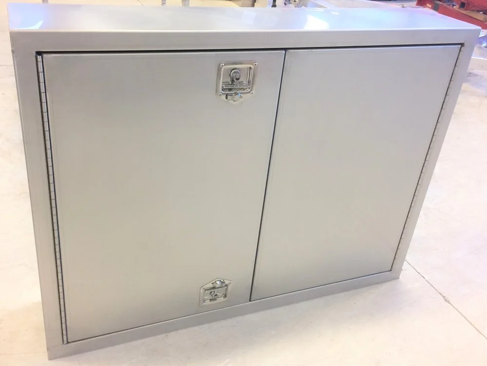
The shell of the cabinet is fabricated entirely of stainless steel: 16 gauge stainless panels with a 2B finish, recessed stainless T-latches, and continuous stainless hinge.
This enclosure was designed to house a hydronic in-floor radiant heat manifold, which runs a heated water solution through a series of tubing installed underneath finished flooring. Focusing most of the effort in the concept and design stages of this project resulted in a superior cabinet that was quick to manufacture and assemble here in our plant, as well as highly practical for installation and service in the field.
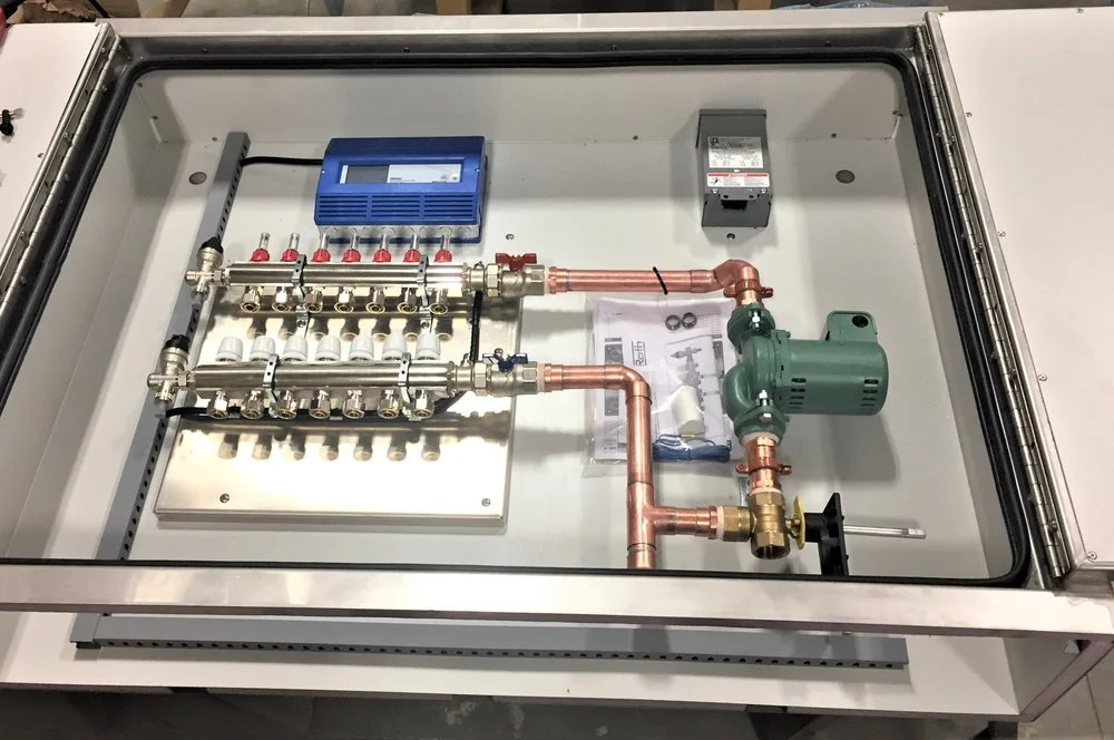
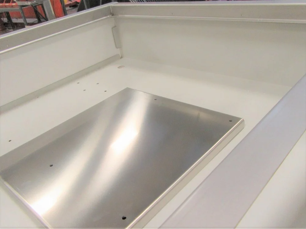
Here is a snapshot of the enclosure with the equipment mounted before it has been installed in the field. Notice the continuous track we installed to house all the wiring, an added feature to keep the space organized and efficient for the final user.
Additional improvements we made over the previous model are as follows:
Flush mount doors and a concealed piano hinge result in a much cleaner look and profile than surface mount doors with the exposed hinge.

Before After
Instead of having to fuss with multiple latches as seen in the ‘before’ picture below, our doors were designed to be integral – one with a rear flange, and the other as an active door with two locking latches. This allows for a complete continuous seal when the doors are closed, while eliminating the center divider to allow for ease of installation and use in the field.

Before After
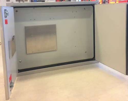
The panel you see mounted in the back of the cabinet serves as a modular equipment mounting plate - the position of this plate can be moved to different locations in the cabinet to allow for different manifold configurations. On the inside of the door is a document pocket. Both of these features are made with aluminum.
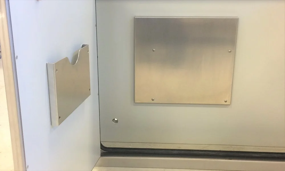
Aluminum offers a high strength-to-weight ratio as well as corrosion resistance. It is also less expensive than stainless steel and much more cost-effective to process.
Here is a great example of design for manufacture - the component pieces of the cabinet were designed so that the flat patterns made the most efficient use of standard sheet sizes. Take a look at this screenshot of a nest we programmed using Sigmanest.

This nest is so efficient that only 7% of this 4x8' sheet of stainless steel becomes scrap. This is an essential aspect of cost reduction in manufacturing.
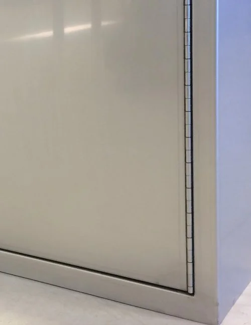
Our bend programs for this cabinet were designed with such tight tolerances, that for certain seams filler wire was not even required when TIG welding.

Here is a close-up of the back side of a door panel. The seam where the two box-and-pan bends come together is impressively precise and narrow.
One of our customer's requirements was for this enclosure to be insulated. We maximized the efficiency of this process in several ways. The individual panels of insulation were designed in Autodesk Inventor, then nested and programmed with Sigmanest. This drastically reduced waste and cut down on labour hours. Not only are the pieces cut perfectly to size every time, but they are also labelled by the router for easy assembly. Below is a video of our CR Onsrud CNC router cutting 1" rigid foam insulation to suit our cabinet. The pictures at the end of the video show the parts being fit together.
To cover the insulation, the cabinet is lined with 22 gauge pre-painted steel. We designed this as a single piece that could be easily slid into place after the insulation was installed.

Side view of the liner
Liner Installed
The design of the liner ensured that it was easy to make, easy to install, and resulted in a better finished product for the end user. In the 'before' picture below, you will notice the protruding ends of the bolts on the inside of the enclosure, compared to the sleek outcome we achieved, seen in the 'after' picture. You can also see the pre-cut mounting holes in the back corners of our model, which allow it to be installed in the field with minimal effort.


Before After
Designing components in one piece can sometimes lead to interference when it comes to physically assembling a product. To test for this, our engineers used the assembly view in Autodesk Inventor, making certain in the design phase that no time would lost in production with parts that do not fit together easily.

Here is a screenshot of the computer model in Autodesk Inventor, where our engineers can click and drag components around to test for possible interference during assembly.
This is a video made in Autodesk Inventor of the enclosure coming together piece by piece.
To achieve our final aim of maximum efficiency - both in our plant and in the field - this cabinet was designed with the fewest number of pieces, as well as the fewest bends, welds, latches, and fasteners. This is an example of simplicity and functionality coming together through clever design to an impressive end.