
NEWS

Recent Main Plant Renovations Update
Phew! We’ve been busy with a massive project over the last 10 months!
Today we’d like to show off some of our recent improvements and renovations that have been done to expand our office spaces to make more room for the future!
MISSION STATEMENT
August 4, 2022
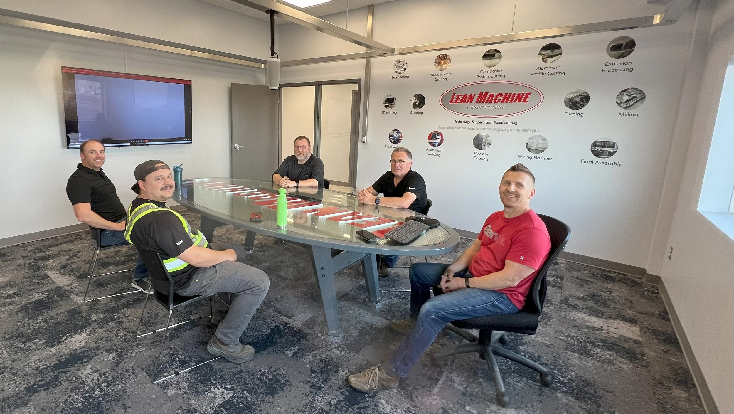
Each year our senior leadership team likes to go offsite to review our goals, objectives, and the main focus of our business. We also use customer and vendor feedback to check how the outside world views us. This year we had a fairly major update in our mission statement and tag line and we liked it so much we printed it on a banner!

FURTHER AUTOMATION IN 3D PRINTING
June 27, 2022
Recently we added our first Ultimaker printer and it has been such a great machine we have purchased their flagship S5 model to our lineup. This printer brings many new features and most importantly automates the switch-over between rolls of material.

This thing is huge! it stands about 4ft tall off the ground.

Material rolls are kept in a humidity controlled cabinet so there is less chance of a print being spoiled by bad material. The machine can automatically switch between rolls when it runs out so no monitoring is needed.

The bed on the S5 is huge at 13” x 9” x 11”
NEW 3D PRINTING CAPABILITY
February 4, 2022
In addition to our super high end Markforged printers (that does carbon fiber printing) we now have an Ultimaker printer that can do high volume parts really quickly out of cheaper materials.


One really cool thing is the “Tree” support function which minimizes the amount of material to support overhangs.
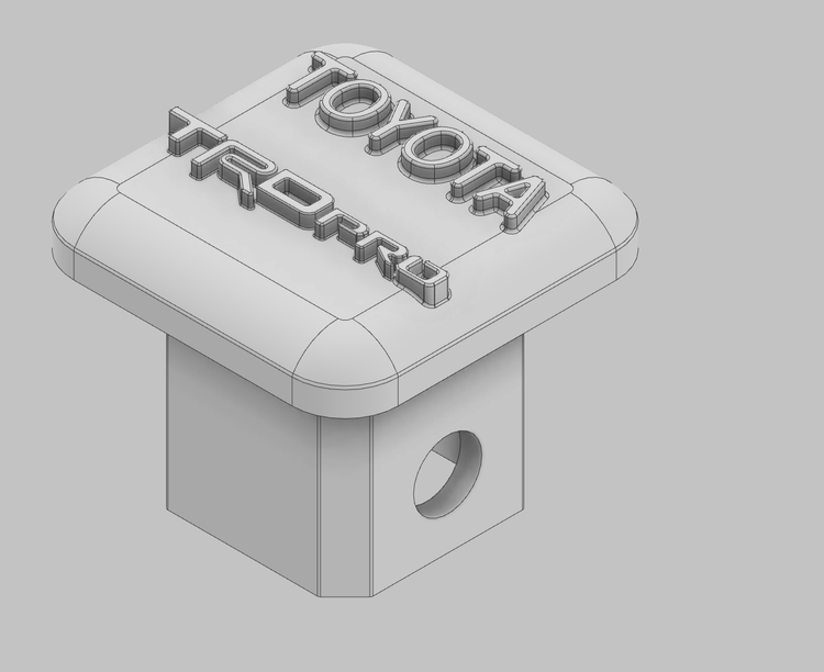
We decided to do some playing to see what the printers capabilities are. Here is a vehicle hitch plug which is a good test part because of the overhang.

A Cura software snapshot with the tree supports

Here is the finished part with the tree supports removed.

It fits!
CATCH ME IF YOU CAN
December 23, 2021
We decided to have a little fun in engineering and update our gingerbread person ornament so we could cut and give out to each of our staff this Christmas. A little extra design went into this one and much debate was had over the expression of the face: is he happy, sneaky, or mean? Below is a quick description of the process to make the ornament happen which is very similar to how we build a lot of our parts at Lean Machine.

It started with drawing in Autodesk Inventor. We tried to pick a shape that would be easy to cut so we didn’t start to cut into production times too badly (can you imagine explaining to a customer their order was late due to the gingerbread person!).

After programming, the process moved to the routers. This is the beauty of having a machine that can depth cut because we can engrave a lot of detail in.


The 2012 version on the left and the 2021 version on the right.
THE WAIT IS OVER, OUR POWDER COATING SYSTEM IS HERE!
December 1, 2021
FOCUS ON CONTINUOUS IMPROVEMENT
September 8, 2020
Continuous improvement activities are performed daily in all areas of the company. The activity selected to be highlighted for the month of August, 2020 is…

NEW PROCESS COMING SOON AND IT WILL BE AUTOMATED!
July 18, 2020
We are still a bit of time away from announcing a new process we are adding but here are some teaser pictures of robot planning. This may give the new process away to some people with a keen eye.

It looks like 10 different robots but it’s actually only 2 with several versions of the arms moved around on a part to check for Robot reach.

These are roughly the same size of robot but one has an extension in between 2 of the joints to have longer reach. This is the largest part we plan on running in this cell so we have to find the balance between running this part and ones much smaller.

We have also been considering concepts for a ventilated enclosure to surround the whole process.
FIRST “LEAN MACHINE” MACHINE
January 1, 2020
After years of buying and integrating machines with our processes we finally decided to build our own machine! A large part of our business is machining aluminum extrusions and some runs involve a lot of human labour so we decided to put together a machine that can run lights-out for long drilling operations. The machine started with a new Yaskawa Motoman robot connected to Yaskawa drives for each of the machine’s axis. The machine is a combination of Lean Machine built (machined, fabricated, 3D printed) and Vention modular frame parts. The picture and video below give a good idea of the early stages of this new cell.

Robot, racks, and machine. Parts are loaded cut to length off a saw, drilled, and then stacked in the proper order in the outbox.
SMALL PART BENDING PART IV
September 9, 2019
In the final post of our Robotic Brake series we will take a quick look at the part chute and error checking plus a video of the overall cell functioning at speed.
We don’t want to have to open the robot cell door to remove parts and we’d like to limit human interaction with the robot. We came up with an idea for a dual chute system and sensors. The robot is programmed to put different part numbers into different chutes plus it checks to make sure a part is present before grabbing the next one in the tray just in case it dropped one or a part got stuck in a bending tool.

Two sensors mounted using 3D printed brackets at the entrance to each chute. The sensors are a double check that the robot successfully grabbed a part, bent it, and got it out of the tooling.

A sheet metal chute loads out into two different part bins.
SMALL PART BENDING PART III
September 2, 2019
In our 3rd part of our Robotic Brake series we are going to take a closer look at tooling.
We have standardized several different tooling sections so we are not swapping tools in and out which eliminates one possible source of error in bending accuracy.
You can see both standard Wilson Tooling and custom 3D printed tools using our incredible Markforged printers. The accuracy and repeatability are unmatched compared to our conventional brakes. The part edge does not touch a back-gauge so there is less error in positioning.

The robot is putting a part into the punch and die set for bending. The Wilson tooling is made at an angle that bending past 90 degrees is possible without changing to “stamping” in the tools.

the drawing says 0.655” and it measures 0.6555”!! This may be a really good part for the picture but we haven’t seen a variance of more than 0.005 and less that 0.25 degrees between parts. On a side note, this is why we don’t use any paper drawings in the shop any more :)

An example of an old steel die (with white protecting tape applied) for a specialty aluminum clip that we produce. This die would last 5000 parts before having to be re-machined into the proper size.

The aluminum clip still in the 3D printed tool set. Not only does this last longer than the steel die (about 10,000 parts) but it will not scratch as much.
SMALL PART BENDING PART II
August 26, 2019
We made a post in December about our new advancements in small part bending. The idea was to offload high volume small bent parts so humans don’t have to stand in front of a machine for hours doing repetitive work. A lot of the small parts we bend require the operator to have their fingers close to the brake press tooling which over long runs of parts can be dangerous. We’ve made some huge leaps forward now that our robot/brake cell is in full production.
The robotic bending project is complicated enough that we will break the updates into several posts. This post will focus on part loading.
One of the first changes we made was blank holding. The flat parts are now put into a tray and loaded in a rack ready to be inserted into the robot cell safely from the outside. The trays allow the robot to know exactly where each part is and grab it. A macro written in the robot allows it to sequence across and then down through the different parts in the tray. The trays are precise enough that a “bad blank” cannot be loaded therefore checking the parts as the operators load them.

An empty tray ready to accept the flat blanks. These trays were put together in house using laser cut panels and 3D printed accessories.

A rack to hold all of the trays. The top section contains different trays and the bottom stores completed parts in Kanban quantities for different customers.

A tray loaded into the cell waiting for processing. The 3 sensors on the left allow the robot to detect which tray has been loading and automatically select which tooling to use.
SMALL PART BENDING AUTOMATION
December 30, 2018
We have set out to build a robotic bending cell! We did an analysis on all of our bent parts and a large percentage of them are small enough to be bent by a robot on a 4ft press brake. Trying to be distruptive in manufacturing, we are stripping the brake of all controls and writing all of the logic into the robot controller. As far as we know, no one has attempted to use a “dumb” brake in combination with a “smart” robot. We found a “no name” press brake and we are using Motomans newest and best material handling robot. We are at the very beginning of this project but wanted to share some progress of the cell coming alive.
One may ask the question; what does Lean Machine know about building equipment? The answer is nothing! We do know our own equipment well and it takes a lot of in-house technical knowledge to keep it performing at it’s peak. We also know how to integrate technology into our customer’s part manufacturing process and this project is an extension of that knowledge. As with all projects at Lean Machine this is to give our customers a better price on parts with a higher level of quality!

This is the first part we want to bend. It’s small so the operator has to over-ride the safety light curtain on each hit which means the activation pedal gets hit twice per bend (4 times per part) which is brutal on an operator when a batch of 500 is the norm.

Here is an overall view of the robot and brake. Lots of wires still hanging around during testing and start up.
CUSTOM WORKHOLDING, COMPOSITE PRINTING
September 8, 2018
At Lean Machine we have recently added a Markforged Composite 3D printer, which has rapidly become a great new tool in our capabilities. Besides the ability to print strong mechanical composite parts for Jigs, Fixtures, Workholding, Tooling, R&D, and other applications, we have been able to make rapid progress in DFAM (Design For Additive Manufacture). We're discovering new opportunities and intricacies in this design process on a daily basis!
One of the greatest abilities of DFAM and Additive Manufacturing is to quickly solve emerging technical challenges around the shop, in an Agile fashion with minimal labour, at the very least without demanding the time of already busy machining centers and conventional production processes. When a new challenge developed on Extrusion processing on our new 5-Axis Gantry CNC, we had just the ticket to solve it...

Our initial configuration for workholding on this machine was based off a previously successful design on another machine, and further improved, consisting of quickly-moveable machine vises down the length of the table. This had proven very effective on the prior generation extrusion workcenter, and we took it a step further with higher quality, more rigid components to maximize the capabilities.
The challenge arose when we realized that to avoid machine collisions, the stickout of many workpieces was such that lighter cutting was required to achieve our standards of cut quality, so our Engineering team got to work on improvements to deliver greater performance. A new "Secondary" vise design was quickly developed in a matter of days, in fact designed entirely around the machine model, to bring the work holding as close to the end cut zones as possible.

This new vise design incorporates Agile and DFAM design theories, and practical expertise from decades of Machining mastery. The choice to build many parts from purpose-engineered reinforced composites is no coincidence: These materials provide excellent dampening to vibrations from high RPM cutting, thereby delivering not only improved cut quality and speeds, but increased tool life as well.
The hard-working mechanical parts that give a vise its clamping capability are of course made from metal alloys, using almost entirely off-the-shelf components (McMaster-Carr in this case, ever-popular among Mech/Mfg Engineers thanks to one-day delivery). Roller thrust bearings, Steel and brass trapezoidal leadscrew components, and special hand-brakes for guideway mounting the vises bring the inner workings together. The vise bases are 5-axis machined in one operation on the same machine they are built for.

Over two dozen 3D printed composite parts are used in each vise, but most of these are small pressed in parts to reinforce fastening areas. The larger parts are reinforced as necessary with either high strength fiberglass, or continuous carbon fiber, in areas that require greater mechanical strength, undergo heavier compressive forces and other stress. Metal components and fasteners can be printed into the parts, or pressed in afterwards. Unlike machined metal parts, the printed parts take substantially less time to program than to design. Printing them can take a days for larger parts, but the process is unmanned and scrapped prints are extremely rare.
Assembly is a breeze, and the vises are ready for service! Thanks to the modular construction, any part that needs to be changed can be swapped on the fly, for example if a particular job requires a different jaw style.
Time to make some chips!
FLEXIBLE OFFICE DESIGN AND RENOVATION
August 25, 2018
When we approached our electrician and said “we are going to rip all of the wires out of our walls” he replied like you would expect: are you crazy? With constant continuous improvement activities, we need the flexibility to move around offices, computers, and machines without having to pull wires through walls and figure out how to patch old holes. It was a little hard to tear apart walls that are only 6 years old but we decided to plan it out and do it anyway.
Our solution to have a more flexible office (and wiring) was to build overhead cable trays. The trays form a halo around each room and all route from the main servers to each area of the plant. Along the way we also made some significant improvements to our ventilation system (positive pressure with an HRV, full zoning of every room, and increased filtration capacity) and found ways to make the offices easier to clean.
CAUTION TO READERS: many terrible *before* pictures to follow and they aren’t pretty!

Step 1: Move everyone out and share offices for a few months. The walls are dark grey with red accents, the ceiling tile is starting to turn brown, and the lights are using way too much power.

Step 2: Rip out wires, run temporary wires, and say “what have we done”! Approximately 150 wires had to be taken out and re-run only to be later run again through the cable tray.

Step 3: take down rest of ceiling tile and finish muddling and taping the ceiling.

After some painting and new flooring we are part way there. Still tough working around all of the mess, wires, and construction noises but we have the greatest people who support progress at any cost! An extra improvement for our people was to switch to up/down desks as seen in this photo.

Done! The hightlights of this picture are: the aluminum cable tray, the LED lights, the light sensor mounted to the bottom of the tray, some new personal storage lockers, lighter grey paint, and exposed ceiling tiles. This renovation also added space for 3 extra people in the same floor plan.

The entire cable tray was designed in-house, built, and installed.

The wire drops from the tray are surface mounted and have a subtle industrial look.
NEW MACHINE ANNOUNCEMENT - 5 AXIS MILLING
July 3, 2018
This week we welcomed a new member to the Lean Machine family, a brand new CR Onsrud 5 axis Gantry mill. This incredible machine will allow us to process aluminum extrusions from all sides in minimal setups.

Put in place and unwrapped the mill is considerably taller than our other machines and the machine fits perfectly in it's new home. This machine features a Fanuc control for X, Y, Z, C, A axis. The gantry is extremely heavy and rigid and features a water cooled spindle.

Shallow cuts that are almost impossible on a saw (and inaccurate on a miter saw) are easily performed. Notice the Kurt Vises mounted to a linear rail for flexability in setup.

PART COUNT REDUCTION
February 18, 2018

Limiting the number of parts required to produce a design saves time, space, confusion, and alleviates jigging concerns. The upright components of this steel weldment would normally be fabricated from 4 miter cut tubes (8 parts per assembly) which would require a lot of careful alignment and handling of many parts.
Rather than fabricating parts in that way, we machine holes and reliefs for bends which brings the 8 parts down to 2. Putting a steel tube across a CNC mill also ensures quality of cut squareness, length, and hole position. Our new bent tube also reduces welding and grinding by 6” (a 25% reduction).
Then, fold it up!

Eat your wheaties.
When a jig is required for final welding, the laser and brake can make quick work of that. This jig features easily interchangeable pieces and bolt together construction.

HEAVY ROUTER MACHINING
December 16, 2017
Our Onsrud CNC Router machines are great at cutting thin sheet, but their heavy build also makes them ideal for machining thicker pieces of aluminum. An advantage of using the router table is that it does not have the machining travel limits inherent in a more typical Vertical Milling Center, such as our HAAS VF4 machine.
This means we are able to machine large parts in one operation, eliminating errors caused by part sensing and greatly reducing setup times. Below is video showing one of our Onsrud routers cutting a new welding jig for our shop out of a ¾” thick sheet of 6061-T6 Aluminum. After deburring, the part is ready to have components installed and be put into use as a robotic welding jig!

MILL AND TURN ALL IN ONE
November 18, 2017
Our awesome new Okuma lathe isn't just a lathe! This machine can turn round parts but can also mill perpendicular and parallel to the part. Here is a video of us making weld flanges for piping assemblies. The entire part is done in one process instead of turning the part in a lathe and then sending to a mill to put the bolt pattern in.

July 14, 2017
This post is a continuation of our previous post: http://www.leanmachinecnc.com/news/2016/12/27/lathe-machining-cost-reduction
Whenever possible, we program our parts on several different machines so they can all be run simultaneously to shorten overall cycle times and give us redundancy of resources.
With our Okuma dual spindle lathe and Autodesk HSM we are able to automate parts that have several operations. The programming and setup time are intense but the result is a part that can run in a fraction of the time with very little human interaction. In this example, we took a part that required several hours of total human attention to a 45 minute unmanned operation.
Here is the Inventor drawing of the part. It's a small brass adapter with different threads on either end.

Moving from CAD to CAM seamlessly is the key to our engineering process. If we change a size in the 3D model the tool path will automatically update. Below is a screenshot of the HSM programming for this part.

Like our previous gang-tool setup this turning strategy uses Iscar's latest technology Pentacut.

The Iscar pentacut uses a 5 sided insert. The insert is a strong design put into a rigid holder and has a chip forming profile which makes for accurate parts and a great finish.
The video below is a run through of the cycle. What the video doesn't show is that the main spindle will bar feed the secondary spindle so we can run a longer bar without interruption.
Below is the finished part ready to ship!

NEW TURNING CENTER!
April 14, 2017
We have a commitment to staying at the leading edge of manufacturing technology. Our newest addition is at the forefront of CNC turning. The Okuma Genos 300-MW is a full CNC lathe with tool changing, live tooling for milling, and a second spindle to finish the backside of a part all in one operation.


Here is a view inside the machine. On the left is the main 10" spindle, center is the tool turret, and the right is a 7" sub-spindle.

The 2nd day into training and we are already getting good parts off! These parts previously would have required a flip in a conventional machine to finish the backside edge. Now the operator can open the door to a finished part.
MACHINING RAW MATERIAL TRANSFER
February 4, 2017
Relating to our previous post about Lathe cost reduction, here is a view into the world of how we transfer our raw material into finished product.

The first step when a work order is posted to the shop floor is to log into our Inventory system and find the correct raw material to use. This computer screen is one terminal that runs a mobile app that we've created. The App can be viewed on any device and is 100% cloud based.

The Inventory tag matches up to the record found in the App.

The material is loaded into one of our saws. Here is the back-end of our Hydmech S23-A band saw. The "-A" in the saw model number denotes it's fully automatic feeding capability.
A very underrated piece of our equipment is our S-23A band saw. This machine can automatically cut to length round bar, flat bar, tube, and pipe by entering in the length and quantity required. This video is cutting 4" sch40 aluminum pipe to length.

Presto, finished parts come out the other end! Not really. Once the raw material processing is complete, many different part routings can take place such as these parts that have been through the saw and lathe.
LATHE MACHINING COST REDUCTION
December 28, 2016
In Machining, a Lathe that changes tools is great but on small parts that have several quick operations there can be more tool change time than spindle-on machining time. A great way to increase spindle-on time and reduce overall cycle time is to tie several tools together in a method known as "gang tooling." Gang tooling planning is very difficult as you need to anticipate the following operations while working on the current one. At Lean Machine, we always go further than most with 3D design because it always pays off in the long run. Since we already have our machines 3D modelled and we can download all tooling off our vendor's website, and every part is drawn in 3D, we can plan out a gang tool very quickly.

The Brass bar hex stock is seen with the finished machined part just needing a part-off operation. The orange block is the gang tool holder that we've designed. You can also see the blue and grey Iscar tools and yellow inserts.

Here is the Autodesk Inventor designed tool block with the HSM tool paths applied.

Our Haas VF4 milling the tool block. This is a steel 3"x3" billet. Iscar's endmills are the greatest!

Lots of internal features to machine but we've designed to be quick to machine.

Here's a close-up of the Iscar tools that will be installed in the block.

All tools installed and ready to machine.

Top view of the block and tools. Notice the dovetail cut on the backside to fit our tool post and the height setting attachment.
ROBOTIC STEEL WELDING
October 24, 2016
Here is a great example of a steel welded assembly at Lean Machine. It's a steel ring with a strengthening rib welded on. As the demand for this part has increased we've applied our standard thinking: if an employee is going to do the same repetitive task over and over (and most likely get extremely tired of doing so) then we need to find a better way to accomplish the task. Our Motoman/Fronius robotic welding cell is always happy to help us automate.


Step 1- Design and build a jig assembly that can make part placement repetitive and accurate. We've used the Motoman positioner in conjunction with the robot to help keep weld angles consistent. Consistent weld angles give us good flux gas (CO2/Argon mix) coverage to make sure welds are not contaminated with atmospheric impurities.

Step 2 - Make the parts themselves better to help with the whole process. Here you can see slots in the ring so the rib can index itself with tabs. On the surface, these parts would be much cheaper to produce out of steel flat-bar but we've decided to laser cut them so we can tightly control tolerances on hole sizes and add trick tab and slot features.

Step 3 - Write a really great robotic welding program in RobotMaster.
Step 4 - Run off parts as quickly as possible!

The resulting weld bead has a good start, nice bead size, proper penetration, and a great crater fill. With all of the parameters available in the Fronius welders you can "tune out" and splatter so the parts need zero clean-up after the weld process and zero anti-splatter coating.
HEAVY STEEL PART FABRICATION
August 20, 2016
Laser cut, bent, and welded steel parts to be light post adapters for civic utility use.

If you look close there is a great edge finish on the 3/4" plate off our HK Laser
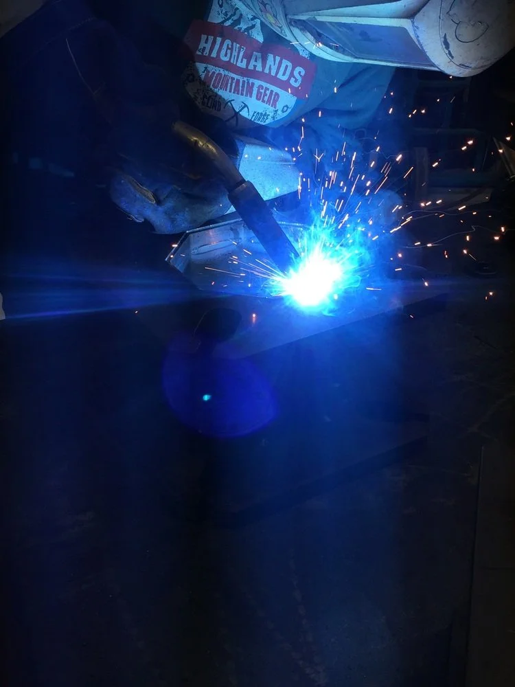
Nothing much to say about this photo other than it's an arty photo of our Fronius welding equipment and one of our super skilled welders.
Below is a video of the part being welded. In the middle of the weld you'll notice there is almost no noise and no spatter which is a great thing! This means that the program we have for the welder to weld 10g plate to 3/4" plate is almost perfect
NEW DEBURRING MACHINE
July 1, 2016
Our new de-buring machine has arrived! This machine takes flat parts that are cut on other machines and breaks the sharp edge. It can also get rid of slag or burrs that are produced during the cutting process.
The machine can also refinish the surface of the material to give it a brushed finish.

Here is an overall view of the machine from HK Laser & Systems. Even though Lean Machine's official color is red, we are starting to get a lot of blue in the shop!

Here inside the machine you can see that large brushes spin and the entire assembly rotates depending on the setting you choose for grain direction, etc.

Here is an aluminum laser cut part about to be fed into the machine. Laser cutting aluminum usually leaves a burr all of the way around the cut edges. A part such as this could take someone approximately 2 minutes to debur properly. The small holes you see in the conveyor are actually vacuum ports which help to hold the part in place while the brushes do their work.

Here is a view of the brushes about to do their work on the part! The shape of the "fingers" on the brushes makes sure that the inside of every hole and cutout are well looked after.

The finished part exiting the machine is completely free of burrs and sharp edges. You'll also notice the large surface of the part has received a slight brushed finish which helps eliminate small scratches on the surface of the part.
COMPRESSOR SHED TURNS INTO HIGH TECH WIND TUNNEL PROJECT
June 18, 2016
We have yet to visit a manufacturing facility (including ours) that does not have a problem with equipment overheating. Compressor and vacuum pumps are definitely the worst for overheating as they run constantly and under full load conditions. It is ideal to keep a noisy compressor outside of the main plant, but protecting the compressor from the elements means possible overheating as it is difficult to build a big enough shed to handle the heat load. Rather than go buy a large sea can or simply build a larger housing, we decided to design and build our very own wind tunnel.

If you are driving by our plant you may notice the new compressor structure off the back of the building. The base is made of steel so the entire structure can be moved easily for future expansion. The bottom side of the steel base has 8" of spray foam insulation.

The north side of the structure is the intake and has louvers to keep driving rain or snow out. The north side intake means prevailing winds help to increase airflow.

Directly behind the intake are slide-out removable filters so all air entering the structure will be free of debris.

Moving inside the structure, the entire intake wall is made of 6 electrically controlled dampers. These dampers open based on the inside temperature so only the necessary amount of air passes through. This is great for the winter months when almost no outside cooling air is needed.

Here is a view of the south wall with 2 of the fans. You can also see the compressor and 2 vacuum pumps installed. We sized the fans to completely exchange the air in the building in 30 seconds. Notice the walls are also lined with white aluminum sheeting so cleaning the entire structure is simple. Behind those walls is 6" of spray foam insulation to stop moisture build up and to make sure that the structure can hold its own temperature no matter what the outside ambient is.

All of the fans and dampers are thermostatically controlled through a custom programmed PLC. At certain set points, dampers are opened and fans turned on so the minimal electricity is used and ideal operating temperatures are maintained.

A gable mounted cross draft fan was installed to add additional cooling as well as draw in warm shop air in the cold winter months to prevent freeze up.

Electricity service to the shed is 600V, and the appropriate transformers are installed to drop down to both 460V and 208V. Notice the use of LED overhead lights to make sure maintainence and electricity use are at a minimum.

Outside the south wall, you can see the flaps open for both one large exhaust fan and the gable fan. As a side note, the white entry doors (left side of picture) were also manufactured in house at Lean Machine!
STEEL AND BLACK POWDER
May 14, 2016
Steel Pipe on the bandsaw, Laser cutting, machining, welding, and some black powder-coating from our friends at Advantage Powder. Sometimes it's hard to believe how many different areas of our production a part can cross. This wasn't robotically welded but thanks to our Fronius Transteel welders you can't tell the difference.

That's a clean looking steel bead layed on this part!
SPHERES AND STREET LAMPS
May 7, 2016
What starts as a really cool aluminum sphere made on one of our CNC lathes is actually the bottom of street lamp brackets all over downtown Saskatoon.


Here is a Google street view of an example of this part. If you can see the bracket attached to the pole, the sphere is opposite the light fixture.
LASER PRECISION BEER
April 16, 2016
Some trick tap handles one of our engineers designed up for a local brewery. We don't normally do smaller jobs like this at Lean Machine but sometimes you have to break the rules. I think the results show that if you have access to the most advanced equipment in the world the possibilities are endless.

Normally cutting 10g thick steel with this much detail would result in a glob of molten metal left on the table but our HK laser and a great programming sequence made it happen. The rear handle is Stainless Steel and the front handle is Mild steel.
STEEL HIGH SPEED MACHINING
March 25, 2016
This post is about a cute little steel part (yes, steel can be cute) that started as a quick brainstorming session in engineering and resulted in a cool finished product for a Saskachewan electronics manufacturer. Even the smallest job at Lean Machine can involve all of management, engineering, administration, and of course our machining department. There are some pretty neat circular machining marks left on the part due to a unique machining method that we will explain below.

This part looks like it could be made from steel flatbar but here at Lean Machine we almost never use pre-cut shapes. This started as a laser cut blank off our HK Laser then we put it through our Haas VF4 mill and this is the resulting part. By not using pre-cut shapes we can reduce our inventory (as you can imagine we would almost never have the correct shape and qty in stock) and shorten our lead times because we can custom cut whatever we need out of a large plate.
Below is the difference between traditional machining vs high speed. The idea is to take smaller (thinner) cuts at a faster rate. We try to achieve a cut with the entire diameter and height of the cutter engaged in order to spread the chip load over the whole tool (instead of just the leading edge). High speed machining also gets super technical by trying to match your cutting frequency with the resonant frequency of the machine but we will leave the explanation of that for another post.

Here is a pretty accurate description of the old (we'll call it traditional to be nice) machining method vs the new better, faster way.

The is a top down view of a cutting tool. By burying the cutter deep into the material you can take thin cuts that load the tool around more of the diameter which distributes the load evenly. Dropping the tool down into the middle of the material used to be a scary thing to do if you just tried to plow through as you would quickly overload the cutter and it would break. Now we can even use smaller (cheaper) tools because they spin faster to eject the chip (and the heat).

We use both MasterCam and Inventor HSM to complete our machine programs. This is a screen shot of what MasterCam calls "Dynamic Milling".
HAPPY ANNIVERSARY TO LEAN MACHINE
March 19, 2016
Lean Machine is officially 10 years old! We have enjoyed every day of the past 10 years (six for Zach and Shaun) and we look forward to the future as there is exciting things to come. We stand by our motto of: A Better Part for a Better Price. There is more automation, leaner processes, added capabilities, and much more to watch for from the team at Lean Machine.

Here is Zach and Shaun doing what they love best....Making chips!
AGGREGATE SAWING
February 21, 2016
An aggregate tool is a combination of a gear box and a right angle adapter. Aggregate tools allow us to drill or cut from the side of a part instead of just from the top on a typical 3 axis machine.

Here is an an example of an aggregate tool. The top of the tool attaches to the spindle and turns at a speed of 10,000 rpm. Different drills or cutting tools can be attached to the collets at either end.

This is a saw blade attached to the aggregate head mounted to the spindle of the machine. The machine is about to cut a part for a customer made from aluminum extrusion. The extrusion is mounted in a custom fixture on our C-axis router.

Here is the finished angle cut on the end of the extrusion. Conventional tools would have to be very long to make a cut like this from the top plane and would not have the great finish and accuracy that the aggregate saw tool has.
CNC WOOD CUTTING
February 13, 2016
Although lean machine regularly cuts metal, we are also more than capable of cutting wood, plastics, and composites!

3/4" MDF being cut on one of our CNC routers for a local kitchen cabinet making shop.

Stacks of consistent and accurate parts on a pallet ready to ship. Notice each one has a label with the part number, thickness, and dimensions.
ASSEMBLIES
January 30, 2016
A huge part of Lean Machine's business is assembling parts. We offer a complete solution to our customers because we can design, cut, machine, bend, weld, and assemble parts. This article is an example of an assembly that we laser cut out of galvanized sheet, bend on a CNC brake, and assemble. To get consistent parts, we also designed and built a jig. The jig was laser cut, welded, machined, and assembled all in our shop.

Here is the jig sitting on an assembly table. Notice the part numbers of each sub-component are laser cut into the jig.

The galvanized steel sub-components are placed on the jig and bolted together.

The stacking method is planned out ahead of time to make sure counting and sorting of completed parts is easy.
NEW MACHINE ANNOUNCEMENT
January 16, 2016
It's been 6 months in the making and we now have our brand new CR Onsrud router! We decided to purchase a new machine to add more aluminum cutting capacity, have the ability to handle larger sheet sizes (up to 8ft wide), and have increased after-hours cutting capacity. This one is a behemoth with a 8' x 20' table. It weighs in around 30,000 lbs and is extremely rigid. The new machine is installed and fully operational.

Here is the table loaded with four 4'x10' sheets of 3/16" aluminum.

We also decided to put the machine through it's paces and cut some 1" thick aluminum right off the start. The tolerance and cut quality is unbelievable!
AUTODESK HSM AND COMPOUND MITER MACHINING
December 6, 2015
The topic of the post is two-fold: one, we need to introduce Lean Machine's integration of Autodesk's HSM programming for all of our mills and lathes; second, we want to show a really cool compound miter cut on the end of a steel tube. Below is a CAD model from Autodesk Inventor. The really neat thing about HSM is that it allows us to program directly inside of Inventor so there is no need to have a translation file in between CAM (Computer Aided Machining), or a separate CAM program.
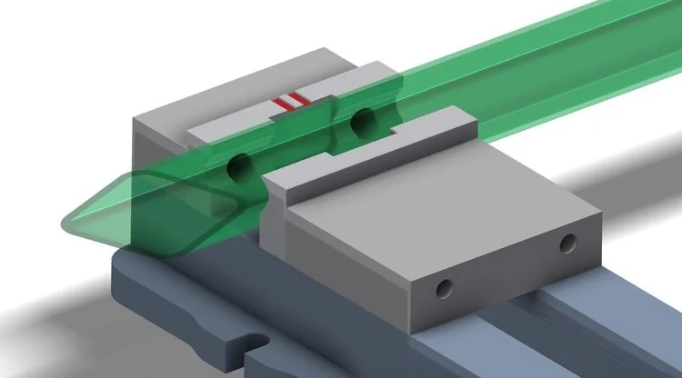
The steel tube that we are going to cut has been changed to semi-transparent for illustration purposes.
Doing a compound cut would normally require a 4 or 5 axis milling machine. Instead, we created angled and twisted jaws for our vises.
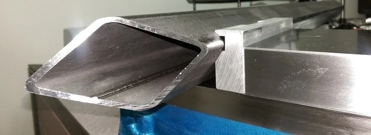
Here is the finished tube mounted in the vise to show how it turns it on the exact angle so the operation can be completed from just one top cutting plane.
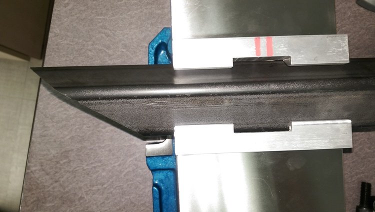
This is the top view of the set-up. Note the marking lines on the back jaw to make sure they go back in the machine correctly. The same marks are in the CAD model, so everything matches when the machinist sets up the job.

This is the top view of the clean precise cut that the mill provides.
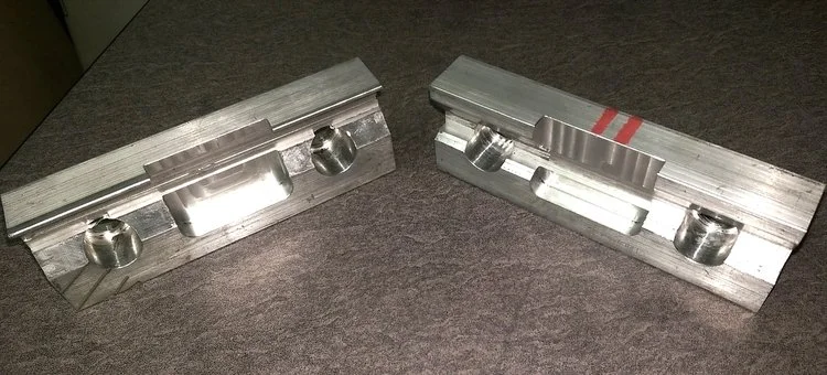
These are the front and back vise jaws removed from the vise; they were machined from solid aluminum.
WELDING AND LABOUR CONTINUOUS IMPROVEMENT
September 21, 2015
Every single day at Lean Machine we work hard to make our customer's parts look better. Also, we need to continually drive down our internal labour costs. Our favorite type of part to improve and automate are the repetitive ones. Every time we are able to automate a process we can re-purpose an employee's position to do something more interesting or increase our capacity. Below you will find a video of robotic welding on aluminum landing gear as well as some before and after pictures of manual versus robotic processes.
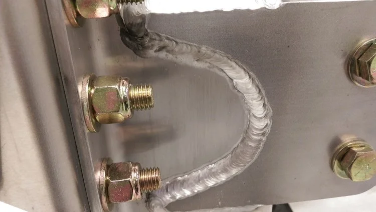
A manual weld on a large arc between 3/8` and 1/8`aluminum plate. This is a great example of a solid manual aluminum weld using Fronius welding equipment. This weld is challenging because the employee has to re-position themselves several times to make sure the correct torch angle is achieved as they move around the arc to ensure the shielding gas is protecting the leading edge of the weld pool.

Here is the after picture of the same parts welded together but using an automated robotic welding cell. The weld has a bit more shine to it mostly due to the perfect torch angle being achieved by the robot`s perfect welding program made directly out of our CAD models. The weld bead size is also perfect every time.
SHOP LAYOUTS
September 7, 2015
Although Lean Machine employs some of the most advanced technology in North America, sometimes it's just easier to use paper to do our planning. We believe this is the essence of Lean Manufacturing - taking the shortest path to the finish line.
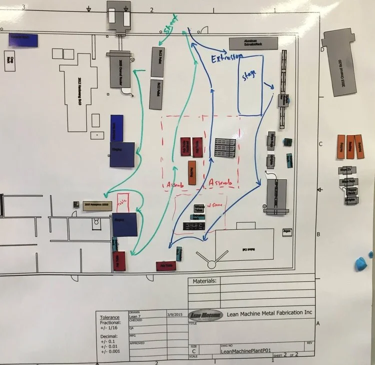
Here is our current layout on an enlarged and laminated drawing.

Here is the start of a new layout. We can do rapid changes using sticky tack and take a picture to record it. If you are really keen, you may notice something new in the picture!
THE ADVANTAGES OF A CNC ROUTER
August 15, 2015
At Lean Machine we have many different ways to cut metal. When cutting aluminum one of our favorite ways is with a CNC router. The router is extremely cost effective to run, it can cut very thick aluminum, and one of the coolest things is that it can depth cut (cut partially down into the sheet) to do engraving and pocketing. Below is a part that we have designed to take advantage of the router's depth cutting capabilities.

This is the base part of an aluminum assembly that is robotically welded together. The half-depth slot is a way to index the gussets that will be welded in without using an additional jig or measuring and tack welding each one in. As a side note, the finished edge quality is excellent on the Onsrud CNC router.

The gusset is a 3/16" thick 5052 aluminum part that is also cut on the CNC Router. The little tab sticking down seems like it is cut on an odd angle; however, much thought was put into the shape of it. The Robot Cell Operator can easily slide each gusset into place, but they will not fall out when the entire assembly rotates in the robotic jig.

NITROGEN LASER CUTTING
July 12, 2015